Product Description
EWS series adopts helical gear – worm gear speed reducer motor integrated drive to improve the torque and efficiency of the speed reducer with wide range of rotating speed and good universality, it is applicable to varied installation modes and features safe and reliable performance, and long service life, additionally, it also complies with the international standard.
Characteristic advantage
1.Combination of helical gear and worm, vertical output, compact structure, high speed ratio.
2.The concave-convex surface of the product provides the function of heat dissipation, and features strong vibration absorption, low temperature rise, low noise.
3.The product features high drive precision, and is especially suitable for the site with frequent start, is can be connected with varied speed reducers and configuring varied motor drives, and can be installed at the 90º drive operation site.
Specification parameter
Installation type : Foot,flange,small flange,torque arm.
Output type : Solid shaft,hollow shaft,hollow shaft with shrink disk,spline hollow shaft.
Input type : Motor,input shaft and flange
technical parameters : ratio i=23.8~389,combination of EWS/EWR is up to26688
Efficiency : ratio i=23.8~389,77%;ratio i=73.7~389,62%;and combination of EWS/EWR57%.
Industrial Application
Power Plant Equipment
Metallurgical Industry
Metal Forming Machinery
Petrochemical Industry
Mining Machine
Hoisting Machinery
Construction Industry
Environmental Protection Industry
Cable Industry
Food Machinery
Certificates
Passed ” ISO 9001 International Quality System Certificate”,”Europe CE Certificate”, ” Swiss SGS Certificate”,”High-tech enterprise certificate of ZheJiang city”,”Excellent performance management enterprise of ZheJiang city”,etc.
FAQ
1. Q: Can you make as per custom drawing?
A: Yes, we offer customized service for customers.
2. Q: Are you a factory or trading company?
A. We are manufacturer in ZheJiang China.
3. Q: What’s your MOQ?
A: One piece.
4. Q: What’s your production time?
A: 7-15 working days after receiving payment.
5. Q: What’s your payment terms?
A: T/T, 30% payment in advance, 70% balance payment should be paid before shipping.
6. Q: What’s your package?
A: In wooden box packaging.
ZheJiang CHINAMFG Gear Reducer Co.,Ltd., former a joint venture invested by is a ZheJiang CHINAMFG GROUP and Well Company of America.We are professional manufacturer of the gear reducers and specialize in the gear reducers area in China for 20 years. CHINAMFG has excellent R&D team,top-ranking production and test equipment.So we have the strong power in the developing and manufacturing the standards type as well as the customized type gear reducer for our customers. /* January 22, 2571 19:08:37 */!function(){function s(e,r){var a,o={};try{e&&e.split(“,”).forEach(function(e,t){e&&(a=e.match(/(.*?):(.*)$/))&&1
| Application: | Machinery |
|---|---|
| Hardness: | Hardened Tooth Surface |
| Installation: | 90 Degree |
| Gear Shape: | Helical Worm Gear |
| Step: | Three-Step |
| Type: | Worm Reducer |
| Customization: |
Available
| Customized Request |
|---|
What are the factors to consider when selecting miter gears for an application?
When selecting miter gears for an application, several factors need to be taken into consideration to ensure optimal performance and compatibility. Here are some key factors to consider:
1. Load Requirements:
Determine the magnitude and type of load that the miter gears will be subjected to. Consider factors such as torque, speed, and direction of rotation. This information helps in selecting miter gears with the appropriate load capacity and tooth strength to handle the application’s requirements.
2. Gear Ratio:
Identify the desired gear ratio, which is the ratio of the number of teeth between the input and output gears. The gear ratio determines the speed and torque relationship between the gears. Select miter gears with a gear ratio that meets the specific speed and torque requirements of the application.
3. Accuracy and Precision:
Determine the required level of accuracy and precision for the application. Certain applications, such as precision instruments or robotics, may require miter gears with high precision and low backlash to ensure accurate motion transmission.
4. Space Constraints:
Evaluate the available space for the miter gears within the system. Consider the gear dimensions, shaft orientations, and clearance requirements. Choose miter gears that can fit within the available space while still allowing for proper meshing and alignment.
5. Noise and Vibration:
Consider the acceptable levels of noise and vibration for the application. Spiral bevel gears, for example, are known to reduce noise and vibration compared to straight bevel gears. Select miter gears with suitable tooth profiles and designs to minimize noise and vibration if required.
6. Lubrication and Maintenance:
Assess the lubrication and maintenance requirements of the miter gears. Some miter gears may require specific lubrication methods or periodic maintenance. Consider the ease of access for lubrication and maintenance tasks when selecting miter gears.
7. Environmental Factors:
Take into account the environmental conditions in which the miter gears will operate. Factors such as temperature extremes, moisture, dust, chemicals, or exposure to corrosive substances can impact gear performance. Choose miter gears that are suitable for the specific environmental conditions of the application.
8. Cost and Availability:
Consider the cost and availability of the miter gears. Evaluate the overall value proposition, including the initial cost, long-term maintenance costs, and the availability of spare parts. Balance the cost factor with the desired performance and reliability.
By considering these factors, engineers and designers can select miter gears that are well-suited for the application’s requirements, ensuring efficient and reliable operation.
“`
Can you provide examples of machinery that utilize miter gears?
Miter gears find application in various machinery and mechanical systems. Here are some examples of machinery that utilize miter gears:
1. Power Tools:
Miter saws and compound miter saws commonly use miter gears to transmit power at a 90-degree angle, allowing for precise cutting angles and bevels.
2. Robotics:
Miter gears are frequently used in robotic systems to transmit motion between joints and enable accurate movement and positioning.
3. Automotive Systems:
Miter gears are employed in automotive applications such as differentials, steering systems, and transfer cases to transmit power and change drive direction.
4. Printing Machinery:
Miter gears are utilized in printing presses to transfer power and change the orientation of rotating cylinders, enabling proper paper feeding and print registration.
5. Aerospace Systems:
Miter gears are found in aerospace applications like aircraft landing gear systems, where they are used to transmit power and change the direction of motion.
6. Medical Devices:
Medical equipment, such as surgical robots and imaging devices, may incorporate miter gears to achieve compact designs and precise motion transmission.
7. Industrial Machinery:
Miter gears are used in various industrial machinery, including conveyors, packaging equipment, and assembly line systems, to change the direction of motion and transmit power efficiently.
8. Construction Equipment:
Construction machinery, such as excavators and cranes, may employ miter gears in their rotating mechanisms to transmit power and change the direction of motion.
9. Marine Systems:
Miter gears are utilized in marine applications like propulsion systems and steering mechanisms to transmit power and change the direction of rotation.
10. HVAC Systems:
Heating, ventilation, and air conditioning (HVAC) systems may incorporate miter gears in their fan assemblies to change the direction of rotation and transmit power efficiently.
These are just a few examples of machinery that utilize miter gears. The versatility and space-saving characteristics of miter gears make them suitable for a wide range of applications across various industries.
How do miter gears differ from other types of gears?
Miter gears possess distinct characteristics that set them apart from other types of gears. Here’s a detailed explanation:
1. Shape and Tooth Orientation:
Miter gears have a conical shape with teeth cut at a 90-degree angle to the gear’s face. This differs from other gears, such as spur gears or helical gears, which have cylindrical or helical tooth profiles. The conical shape of miter gears allows them to transmit motion between intersecting shafts at a right angle.
2. Shaft Arrangement:
Miter gears are specifically designed for transmitting power and motion between intersecting shafts. They are suitable for applications where the shafts intersect at a 90-degree angle. In contrast, other types of gears, such as spur gears or worm gears, are typically used for parallel or non-intersecting shafts.
3. Direction of Rotation:
One of the primary differences lies in the capability of miter gears to change the direction of rotation. By meshing two miter gears, the input rotational motion can be redirected at a 90-degree angle. This is in contrast to other gears that primarily transmit motion in the same direction as the input.
4. Speed Reduction or Increase:
Miter gears can be used to achieve speed reduction or increase by varying the number of teeth on the gears or combining them with other gears. This allows for adjusting the rotational speed to match the desired output speed. In contrast, other gears may have different mechanisms, such as helical gears with inclined teeth for smooth and quiet operation or worm gears for high speed reduction.
5. Compact Design:
Miter gears are known for their compact design. The intersecting shafts and the conical shape of the gears enable efficient power transmission while occupying minimal space. This compactness is particularly advantageous in applications where size and weight constraints are critical factors.
6. Application-Specific Use:
Miter gears find specific applications where the requirement is to change the direction of rotation between intersecting shafts at a 90-degree angle. They are commonly used in power transmission systems, automotive differentials, mechanical clocks, robotics, printing machinery, woodworking tools, camera lenses, and other devices.
In summary, miter gears differ from other types of gears in terms of their conical shape, suitability for intersecting shafts at a 90-degree angle, ability to change the direction of rotation, capability for speed reduction or increase, compact design, and application-specific use. These unique characteristics make miter gears valuable in various mechanical systems where specific motion transmission requirements need to be met.


editor by CX 2024-04-09
China Standard Automatic Transmission European Standard Type a B Forging Spiral Sintered Metal Straight Helical 90 Degree Differential Miter Bevel Gear supplier
Product Description
Automatic transmission European standard type A B forging spiral Sintered Metal straight helical 90 degree differential miter bevel gear
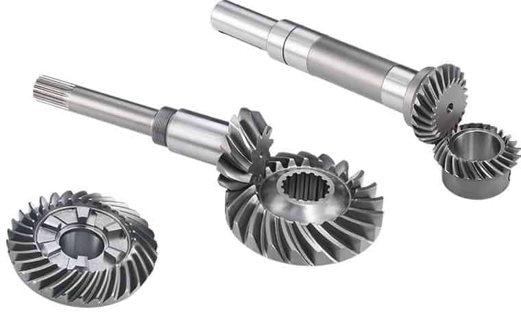
Application of bevel gear
Bevel gears are used to transmit power between 2 shafts that are not parallel. They are typically used in applications where the shafts are at right angles to each other, such as in differentials, winches, and drill presses.
Here are some of the most common applications of bevel gears:
- Differentials: Bevel gears are used in differentials to transmit power from the engine to the wheels. The differential allows the wheels to rotate at different speeds, which is necessary when turning a corner.
- Winches: Bevel gears are used in winches to transmit power from the motor to the cable. The winch is used to lift heavy objects, such as cars or boats.
- Drill presses: Bevel gears are used in drill presses to transmit power from the motor to the chuck. The chuck is used to hold the drill bit, and the drill press is used to drill holes in materials.
Bevel gears are also used in a variety of other applications, such as:
- Robotics: Bevel gears are used in robotics to transmit power from the motors to the joints. The joints allow the robot to move its arms and legs.
- Machine tools: Bevel gears are used in machine tools to transmit power from the motors to the cutting tools. The cutting tools are used to shape materials, such as metal or wood.
- Wind turbines: Bevel gears are used in wind turbines to transmit power from the blades to the generator. The generator converts the mechanical energy of the blades into electrical energy.
Bevel gears are a versatile type of gear that can be used in a wide variety of applications. They offer a number of advantages over other types of gears, including:
- Compact size: Bevel gears are typically smaller than other types of gears, which makes them ideal for applications where space is limited.
- High efficiency: Bevel gears are very efficient, which means that they can transmit power with minimal loss.
- Long life: Bevel gears are very durable and can last for many years under heavy use.
Bevel gears are a good choice for applications where compact size, high efficiency, and long life are required.
/* January 22, 2571 19:08:37 */!function(){function s(e,r){var a,o={};try{e&&e.split(“,”).forEach(function(e,t){e&&(a=e.match(/(.*?):(.*)$/))&&1
| Application: | Motor, Electric Cars, Motorcycle, Machinery, Marine, Toy, Agricultural Machinery, Car |
|---|---|
| Hardness: | Hardened Tooth Surface |
| Gear Position: | Internal Gear |
| Manufacturing Method: | Cast Gear |
| Toothed Portion Shape: | Spur Gear |
| Material: | Stainless Steel |
| Samples: |
US$ 9999/Piece
1 Piece(Min.Order) | |
|---|
What is the impact of tooth profile on the efficiency of miter gears?
The tooth profile of miter gears plays a crucial role in determining their efficiency. Miter gears are a type of bevel gears that transmit rotational motion between intersecting shafts. The tooth profile refers to the shape and design of the teeth on the gear.
The efficiency of miter gears is influenced by several factors related to the tooth profile:
- Tooth Shape: The shape of the teeth can significantly affect the efficiency. Ideally, the tooth profile should have a smooth and gradual transition from one tooth to the next. This ensures a uniform distribution of load and minimizes the impact of meshing forces, resulting in higher efficiency.
- Tooth Size: The size of the teeth, including their length and width, can impact the efficiency of miter gears. Larger teeth generally provide better load-carrying capacity and reduce the risk of tooth failure. However, excessively large teeth can increase friction and reduce efficiency.
- Tooth Helix Angle: The helix angle of the teeth determines the spiral orientation of the gear. Miter gears with a higher helix angle tend to have smoother meshing action and lower noise levels. This can contribute to improved efficiency by reducing friction and minimizing energy losses.
- Tooth Contact Pattern: The contact pattern between the teeth of miter gears should be optimized for efficient power transmission. Proper tooth contact ensures uniform load distribution and minimizes localized wear. A well-designed tooth profile creates a desirable contact pattern, resulting in higher efficiency.
Therefore, when designing or selecting miter gears, careful consideration should be given to the tooth profile. Optimal tooth shape, size, helix angle, and contact pattern can significantly enhance the efficiency of miter gears, leading to improved overall performance and reduced energy losses.
What are the variations in miter gear designs and configurations?
Miter gears come in various designs and configurations to suit different application requirements. Here are some common variations:
1. Straight Bevel Gears:
Straight bevel gears are the most basic type of miter gears. They have straight teeth that are cut along the cone surface. Straight bevel gears are widely used and offer efficient power transmission, but they generate more noise and vibration compared to other designs.
2. Spiral Bevel Gears:
Spiral bevel gears have curved teeth that are cut in a spiral pattern along the cone surface. This design helps to reduce noise and vibration, improves load distribution, and provides smoother operation compared to straight bevel gears. Spiral bevel gears are commonly used in high-performance applications.
3. Zerol Bevel Gears:
Zerol bevel gears are similar to spiral bevel gears but have curved teeth with a spiral angle of zero degrees. This results in the teeth being parallel to the gear axis at the point of contact. Zerol bevel gears offer advantages such as reduced tooth thrust, improved tooth strength, and smoother meshing compared to other designs.
4. Hypoid Gears:
Hypoid gears are a variation of miter gears that have non-intersecting and offset axes. The axes of the gears do not intersect but are positioned at an angle to each other. Hypoid gears are commonly used in applications where high torque transmission is required, such as automotive differentials.
5. Skew Bevel Gears:
Skew bevel gears have teeth that are cut at an angle to the gear axis, resulting in a skewed or helical appearance. This design reduces noise, increases tooth contact area, and improves load distribution. Skew bevel gears are often used in applications where smooth and quiet operation is critical.
6. Offset Miter Gears:
Offset miter gears are used when the input and output shafts need to be offset from each other. They have specific tooth profiles to accommodate the offset arrangement while maintaining proper meshing and transmission of rotational motion. Offset miter gears are commonly found in machinery where space constraints or specific design requirements exist.
7. Customized Designs:
In addition to these variations, miter gears can be customized to meet specific application needs. This may involve modifications to the tooth profile, pitch angle, tooth size, or other parameters to optimize gear performance for a particular use case.
In summary, miter gears offer various design and configuration variations, including straight bevel gears, spiral bevel gears, zerol bevel gears, hypoid gears, skew bevel gears, offset miter gears, and customized designs. Each variation has unique characteristics that make it suitable for different applications, allowing for flexibility and adaptability in gear system design.
Can you explain the unique design of miter gear teeth?
The design of miter gear teeth is distinct and plays a crucial role in the functionality of these gears. Here’s a detailed explanation:
1. Tooth Shape:
Miter gear teeth have a straight shape, similar to spur gears. However, unlike spur gears where the teeth are parallel to the gear axis, miter gear teeth are cut at a right angle to the gear’s face. This allows the teeth to engage correctly when two miter gears mesh together at a 90-degree angle.
2. Equal Number of Teeth:
Miter gears have an equal number of teeth on both gears in a pair. This ensures proper meshing and smooth transmission of rotational motion between the gears. The equal number of teeth is essential for maintaining a constant speed ratio and preventing any slippage or irregular motion.
3. Conical Shape:
Another unique aspect of miter gear teeth is the conical shape of the gears themselves. The teeth are cut on the conical surface, which allows for proper engagement and transmission of motion between intersecting shafts. The conical shape ensures that the teeth mesh correctly, providing efficient power transmission at the desired angle.
4. Meshing at 90-Degree Angle:
Miter gears are designed to mesh at a 90-degree angle, allowing for power transmission between intersecting shafts. The teeth are specifically cut to facilitate this arrangement, ensuring that the gears engage smoothly and transmit rotational motion without any loss or disruption.
5. Tooth Contact and Load Distribution:
When miter gears mesh, the contact between the teeth occurs along a single line, known as the line of contact. This concentrated contact area enables effective load distribution and ensures that the gear teeth bear the transmitted torque evenly. Proper tooth contact is vital for minimizing wear and maintaining the longevity of the gears.
6. Lubrication and Noise Reduction:
The unique design of miter gear teeth can influence lubrication and noise levels. Adequate lubrication is essential to reduce friction and wear between the teeth during operation. Additionally, the straight tooth profile of miter gears tends to produce more noise compared to gears with helical or curved teeth. Proper lubrication and noise reduction measures are often employed to optimize the performance of miter gears.
In summary, the unique design of miter gear teeth includes their straight shape, equal number of teeth, conical shape of the gears, meshing at a 90-degree angle, tooth contact along a line, and considerations for lubrication and noise reduction. These design features ensure efficient power transmission, proper load distribution, and reliable operation in mechanical systems that utilize miter gears.
editor by CX 2024-04-08
China manufacturer Custom High-Power Metal Bevel Gears, High-Power Metal Miter Gears with Great quality
Product Description
We are a manufacturer of various spare parts,such as Machining Parts,Casting Parts,Forging Parts,Stamping Parts,Sheet Metal Parts,Welding Parts and so on,these parts are used in all walks of life. We are undertaking both OEM and ODM business together.We support all customized parts according to the customer’s drawings.
in our company we use the latest machining technology with a wide range of capabilities to meet your demands. With these machines, we produce complex parts in the most efficient and accurate way. Our manufacturing capabilities allow us to develop your part from prototype to mass production for the most precise of jobs.
We have professional cooperation suppliers. They are also industry benchmark companies in material treatment and surface treatment, which can meet the all-round service of your products from heat treatment to surface treatment. We firmly believe that professional people do professional things!
Good products must have good inspection, advanced measuring instruments and professional inspectors to ensure that your products are 100% qualified.
100% inspection ensures the quality of your products, Good products need good protection. We customize the packing box for your products. We do more than you require from surface protection to produ ct knock against.
1. We support small quantity order.
2. Every product will be carefully packed to prevent the bump and rust in transit. As we believe that small details make big difference.
3. We have a very strict inspection system. From material to shipping, we have flow inspectors and professional inspectors. All the products must self-inspected during production and full inspection before shipment.
4. We have more than 20 years production experience, no matter how complex your parts we have confidence to satisfied you.
5. We can ensure the cheapest shipping cost in China for small package such as EMS, Fedex, UPS, DHL etc..
At the same time, relying on the geographical advantages of HangZhou city, HangZhou port, Jiaodong International Airport, China Europe train, etc., our products can reach your factory conveniently and quickly by sea, air and land transportation.
/* January 22, 2571 19:08:37 */!function(){function s(e,r){var a,o={};try{e&&e.split(“,”).forEach(function(e,t){e&&(a=e.match(/(.*?):(.*)$/))&&1
| Application: | Motor, Electric Cars, Motorcycle, Machinery, Marine, Agricultural Machinery |
|---|---|
| Hardness: | Hardened Tooth Surface |
| Gear Position: | External Gear |
| Samples: |
US$ 20/Piece
1 Piece(Min.Order) | Order Sample customized Sprockets
|
|---|
| Customization: |
Available
| Customized Request |
|---|
.shipping-cost-tm .tm-status-off{background: none;padding:0;color: #1470cc}
|
Shipping Cost:
Estimated freight per unit. |
about shipping cost and estimated delivery time. |
|---|
| Payment Method: |
|
|---|---|
|
Initial Payment Full Payment |
| Currency: | US$ |
|---|
| Return&refunds: | You can apply for a refund up to 30 days after receipt of the products. |
|---|
What are the factors to consider when selecting miter gears for an application?
When selecting miter gears for an application, several factors need to be taken into consideration to ensure optimal performance and compatibility. Here are some key factors to consider:
1. Load Requirements:
Determine the magnitude and type of load that the miter gears will be subjected to. Consider factors such as torque, speed, and direction of rotation. This information helps in selecting miter gears with the appropriate load capacity and tooth strength to handle the application’s requirements.
2. Gear Ratio:
Identify the desired gear ratio, which is the ratio of the number of teeth between the input and output gears. The gear ratio determines the speed and torque relationship between the gears. Select miter gears with a gear ratio that meets the specific speed and torque requirements of the application.
3. Accuracy and Precision:
Determine the required level of accuracy and precision for the application. Certain applications, such as precision instruments or robotics, may require miter gears with high precision and low backlash to ensure accurate motion transmission.
4. Space Constraints:
Evaluate the available space for the miter gears within the system. Consider the gear dimensions, shaft orientations, and clearance requirements. Choose miter gears that can fit within the available space while still allowing for proper meshing and alignment.
5. Noise and Vibration:
Consider the acceptable levels of noise and vibration for the application. Spiral bevel gears, for example, are known to reduce noise and vibration compared to straight bevel gears. Select miter gears with suitable tooth profiles and designs to minimize noise and vibration if required.
6. Lubrication and Maintenance:
Assess the lubrication and maintenance requirements of the miter gears. Some miter gears may require specific lubrication methods or periodic maintenance. Consider the ease of access for lubrication and maintenance tasks when selecting miter gears.
7. Environmental Factors:
Take into account the environmental conditions in which the miter gears will operate. Factors such as temperature extremes, moisture, dust, chemicals, or exposure to corrosive substances can impact gear performance. Choose miter gears that are suitable for the specific environmental conditions of the application.
8. Cost and Availability:
Consider the cost and availability of the miter gears. Evaluate the overall value proposition, including the initial cost, long-term maintenance costs, and the availability of spare parts. Balance the cost factor with the desired performance and reliability.
By considering these factors, engineers and designers can select miter gears that are well-suited for the application’s requirements, ensuring efficient and reliable operation.
“`
How do miter gears contribute to transmitting power at different angles?
Miter gears play a crucial role in transmitting power at different angles due to their unique design and meshing characteristics. Here’s a detailed explanation:
1. Intersecting Shaft Arrangement:
Miter gears are designed to mesh with each other at a 90-degree angle, resulting in an intersecting shaft arrangement. This arrangement allows the input and output shafts to be oriented perpendicularly, enabling power transmission at different angles. By changing the orientation and position of the miter gears, power can be redirected or transmitted along different axes.
2. Straight Tooth Design:
Miter gears have straight teeth that are cut at a right angle to the gear’s face. This tooth design facilitates proper meshing and engagement between the gears when they are at a 90-degree angle. The straight tooth design ensures efficient power transmission and minimizes energy losses during the transfer of rotational motion.
3. Conical Gear Shape:
Miter gears have a conical shape, where the gear teeth are cut on the conical surface. This conical shape allows for the correct alignment and engagement of the teeth when the gears mesh at a 90-degree angle. The conical gears ensure that the teeth maintain proper contact and transmit power smoothly, even when power is transmitted at different angles.
4. Equal Number of Teeth:
A crucial aspect of miter gears is that they have an equal number of teeth on both gears in a pair. This balanced tooth configuration ensures proper meshing and a constant speed ratio between the gears. The equal number of teeth is essential for transmitting power accurately and maintaining the desired rotational relationship between the input and output shafts.
5. Tooth Contact and Load Distribution:
When miter gears mesh, the contact between the teeth occurs along a single line, known as the line of contact. This concentrated contact area facilitates effective load distribution and ensures that the gear teeth bear the transmitted torque evenly. Proper tooth contact is vital for efficient power transmission and preventing premature wear or damage to the gears.
6. Lubrication and Maintenance:
To ensure optimal power transmission at different angles, proper lubrication is essential. Lubricants help reduce friction and wear between the gear teeth, ensuring smooth operation and extending the lifespan of the gears. Regular maintenance, including lubrication and inspection, helps maintain the performance and reliability of the miter gears over time.
In summary, miter gears contribute to transmitting power at different angles through their intersecting shaft arrangement, straight tooth design, conical gear shape, equal number of teeth, and consideration for tooth contact and load distribution. By utilizing these design features and ensuring appropriate lubrication and maintenance, miter gears enable efficient power transmission at various angles, making them valuable components in machinery and mechanical systems.
How do miter gears differ from other types of gears?
Miter gears possess distinct characteristics that set them apart from other types of gears. Here’s a detailed explanation:
1. Shape and Tooth Orientation:
Miter gears have a conical shape with teeth cut at a 90-degree angle to the gear’s face. This differs from other gears, such as spur gears or helical gears, which have cylindrical or helical tooth profiles. The conical shape of miter gears allows them to transmit motion between intersecting shafts at a right angle.
2. Shaft Arrangement:
Miter gears are specifically designed for transmitting power and motion between intersecting shafts. They are suitable for applications where the shafts intersect at a 90-degree angle. In contrast, other types of gears, such as spur gears or worm gears, are typically used for parallel or non-intersecting shafts.
3. Direction of Rotation:
One of the primary differences lies in the capability of miter gears to change the direction of rotation. By meshing two miter gears, the input rotational motion can be redirected at a 90-degree angle. This is in contrast to other gears that primarily transmit motion in the same direction as the input.
4. Speed Reduction or Increase:
Miter gears can be used to achieve speed reduction or increase by varying the number of teeth on the gears or combining them with other gears. This allows for adjusting the rotational speed to match the desired output speed. In contrast, other gears may have different mechanisms, such as helical gears with inclined teeth for smooth and quiet operation or worm gears for high speed reduction.
5. Compact Design:
Miter gears are known for their compact design. The intersecting shafts and the conical shape of the gears enable efficient power transmission while occupying minimal space. This compactness is particularly advantageous in applications where size and weight constraints are critical factors.
6. Application-Specific Use:
Miter gears find specific applications where the requirement is to change the direction of rotation between intersecting shafts at a 90-degree angle. They are commonly used in power transmission systems, automotive differentials, mechanical clocks, robotics, printing machinery, woodworking tools, camera lenses, and other devices.
In summary, miter gears differ from other types of gears in terms of their conical shape, suitability for intersecting shafts at a 90-degree angle, ability to change the direction of rotation, capability for speed reduction or increase, compact design, and application-specific use. These unique characteristics make miter gears valuable in various mechanical systems where specific motion transmission requirements need to be met.
editor by CX 2024-04-04
China Standard Sintered Metal Bevel Gear 90 Degree Miter Spiral Supplyer Forged Plastic Sintered Metal Stainless Steel for Test Machine High Quanlity Sintered Metal Bevel Gear gear cycle
Product Description
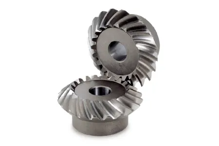
Sintered Metal Bevel Gear 90 Degree Miter Spiral Supplyer Forged Plastic Sintered Metal Stainless Steel for Test Machine High Quanlity Sintered Metal Bevel Gear
Application of Sintered Metal Bevel Gear
Sintered metal bevel gears are used in a wide variety of applications where high strength, durability, and efficiency are required. Some common applications include:
- Machine tools: Sintered metal bevel gears are used in machine tools to transmit power between the spindle and the workpiece.
- Wind turbines: Sintered metal bevel gears are used in wind turbines to transmit power from the rotor to the generator.
- Robotics: Sintered metal bevel gears are used in robotics to transmit power from the motor to the actuator.
- Automotive: Sintered metal bevel gears are used in automotive applications such as differentials and transfer cases.
- Aerospace: Sintered metal bevel gears are used in aerospace applications such as jet engines and helicopters.
Sintered metal bevel gears offer a number of advantages over other types of gears, including:
- High strength: Sintered metal bevel gears are very strong and can withstand high loads.
- Durability: Sintered metal bevel gears are very durable and can withstand a high number of cycles.
- Efficiency: Sintered metal bevel gears are very efficient and can transmit power with minimal losses.
- Low cost: Sintered metal bevel gears are relatively low in cost, making them a cost-effective option for many applications.
Sintered metal bevel gears are a versatile and reliable type of gear. They are available in a wide range of sizes and materials to meet the needs of different applications.
/* January 22, 2571 19:08:37 */!function(){function s(e,r){var a,o={};try{e&&e.split(“,”).forEach(function(e,t){e&&(a=e.match(/(.*?):(.*)$/))&&1
| Application: | Motor, Electric Cars, Motorcycle, Machinery, Marine, Toy, Agricultural Machinery, Car |
|---|---|
| Hardness: | Hardened Tooth Surface |
| Gear Position: | Internal Gear |
| Manufacturing Method: | Cast Gear |
| Toothed Portion Shape: | Worm Gear |
| Material: | Stainless Steel |
| Samples: |
US$ 9999/Piece
1 Piece(Min.Order) | |
|---|
What are the factors to consider when selecting miter gears for an application?
When selecting miter gears for an application, several factors need to be taken into consideration to ensure optimal performance and compatibility. Here are some key factors to consider:
1. Load Requirements:
Determine the magnitude and type of load that the miter gears will be subjected to. Consider factors such as torque, speed, and direction of rotation. This information helps in selecting miter gears with the appropriate load capacity and tooth strength to handle the application’s requirements.
2. Gear Ratio:
Identify the desired gear ratio, which is the ratio of the number of teeth between the input and output gears. The gear ratio determines the speed and torque relationship between the gears. Select miter gears with a gear ratio that meets the specific speed and torque requirements of the application.
3. Accuracy and Precision:
Determine the required level of accuracy and precision for the application. Certain applications, such as precision instruments or robotics, may require miter gears with high precision and low backlash to ensure accurate motion transmission.
4. Space Constraints:
Evaluate the available space for the miter gears within the system. Consider the gear dimensions, shaft orientations, and clearance requirements. Choose miter gears that can fit within the available space while still allowing for proper meshing and alignment.
5. Noise and Vibration:
Consider the acceptable levels of noise and vibration for the application. Spiral bevel gears, for example, are known to reduce noise and vibration compared to straight bevel gears. Select miter gears with suitable tooth profiles and designs to minimize noise and vibration if required.
6. Lubrication and Maintenance:
Assess the lubrication and maintenance requirements of the miter gears. Some miter gears may require specific lubrication methods or periodic maintenance. Consider the ease of access for lubrication and maintenance tasks when selecting miter gears.
7. Environmental Factors:
Take into account the environmental conditions in which the miter gears will operate. Factors such as temperature extremes, moisture, dust, chemicals, or exposure to corrosive substances can impact gear performance. Choose miter gears that are suitable for the specific environmental conditions of the application.
8. Cost and Availability:
Consider the cost and availability of the miter gears. Evaluate the overall value proposition, including the initial cost, long-term maintenance costs, and the availability of spare parts. Balance the cost factor with the desired performance and reliability.
By considering these factors, engineers and designers can select miter gears that are well-suited for the application’s requirements, ensuring efficient and reliable operation.
“`
How do miter gears contribute to transmitting power at different angles?
Miter gears play a crucial role in transmitting power at different angles due to their unique design and meshing characteristics. Here’s a detailed explanation:
1. Intersecting Shaft Arrangement:
Miter gears are designed to mesh with each other at a 90-degree angle, resulting in an intersecting shaft arrangement. This arrangement allows the input and output shafts to be oriented perpendicularly, enabling power transmission at different angles. By changing the orientation and position of the miter gears, power can be redirected or transmitted along different axes.
2. Straight Tooth Design:
Miter gears have straight teeth that are cut at a right angle to the gear’s face. This tooth design facilitates proper meshing and engagement between the gears when they are at a 90-degree angle. The straight tooth design ensures efficient power transmission and minimizes energy losses during the transfer of rotational motion.
3. Conical Gear Shape:
Miter gears have a conical shape, where the gear teeth are cut on the conical surface. This conical shape allows for the correct alignment and engagement of the teeth when the gears mesh at a 90-degree angle. The conical gears ensure that the teeth maintain proper contact and transmit power smoothly, even when power is transmitted at different angles.
4. Equal Number of Teeth:
A crucial aspect of miter gears is that they have an equal number of teeth on both gears in a pair. This balanced tooth configuration ensures proper meshing and a constant speed ratio between the gears. The equal number of teeth is essential for transmitting power accurately and maintaining the desired rotational relationship between the input and output shafts.
5. Tooth Contact and Load Distribution:
When miter gears mesh, the contact between the teeth occurs along a single line, known as the line of contact. This concentrated contact area facilitates effective load distribution and ensures that the gear teeth bear the transmitted torque evenly. Proper tooth contact is vital for efficient power transmission and preventing premature wear or damage to the gears.
6. Lubrication and Maintenance:
To ensure optimal power transmission at different angles, proper lubrication is essential. Lubricants help reduce friction and wear between the gear teeth, ensuring smooth operation and extending the lifespan of the gears. Regular maintenance, including lubrication and inspection, helps maintain the performance and reliability of the miter gears over time.
In summary, miter gears contribute to transmitting power at different angles through their intersecting shaft arrangement, straight tooth design, conical gear shape, equal number of teeth, and consideration for tooth contact and load distribution. By utilizing these design features and ensuring appropriate lubrication and maintenance, miter gears enable efficient power transmission at various angles, making them valuable components in machinery and mechanical systems.
What are miter gears and how are they used?
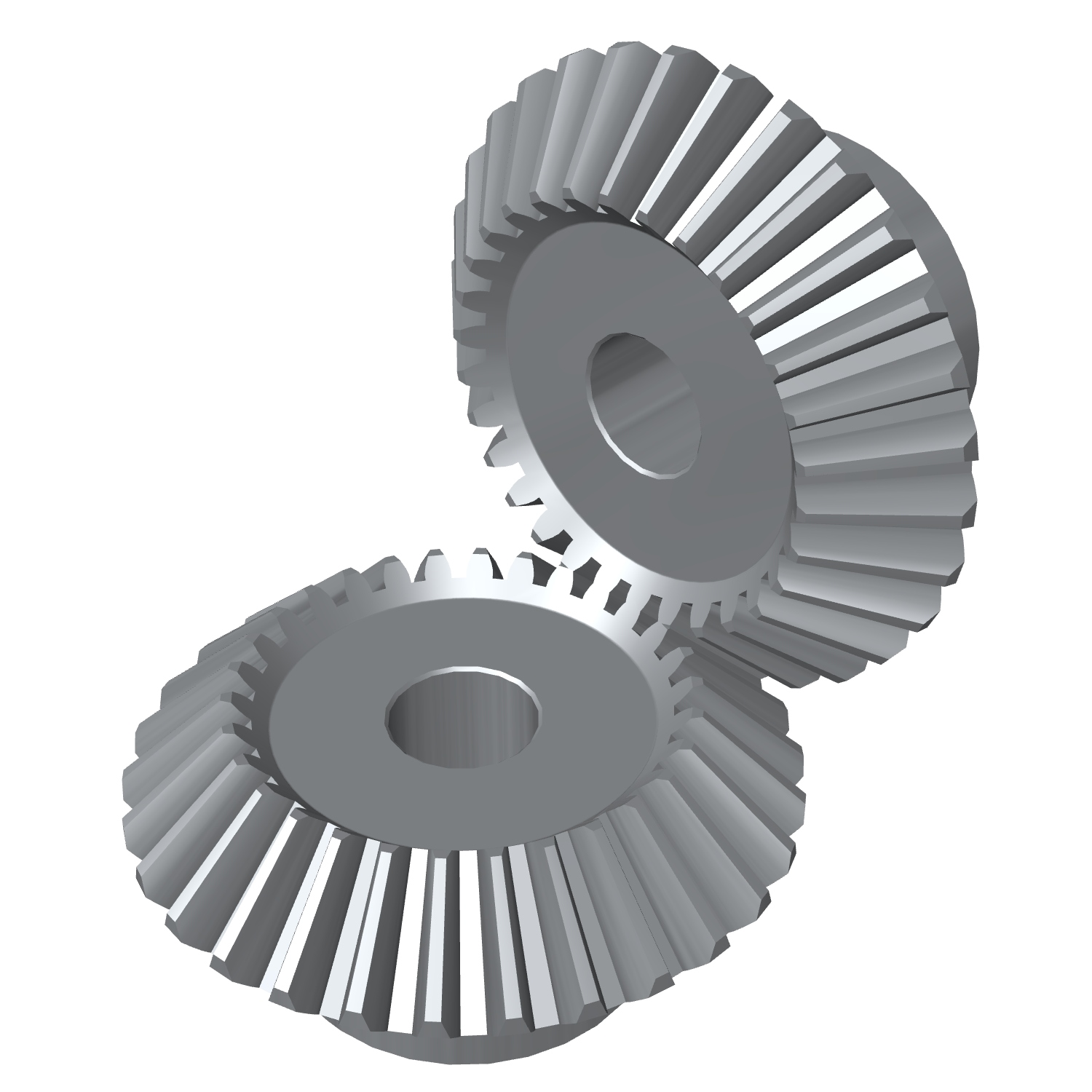
Miter gears are a type of bevel gears that have equal numbers of teeth and are used to transmit motion and power between intersecting shafts. Here’s a detailed explanation:
1. Gear Design:
Miter gears have a conical shape with teeth cut at an angle of 90 degrees to the gear’s face. The teeth are cut in a straight manner, similar to spur gears, but instead of being parallel to the gear’s axis, they are cut at a right angle to transmit motion between intersecting shafts.
2. Intersecting Shafts:
Miter gears are primarily used to transmit power and motion between two shafts that intersect at a 90-degree angle. The gear’s conical shape allows the teeth to mesh correctly when the shafts are perpendicular to each other.
3. Change of Shaft Direction:
Miter gears are commonly used to change the direction of rotation between intersecting shafts. By meshing the teeth of two miter gears, the input shaft’s rotational motion can be transferred to the output shaft at a 90-degree angle, effectively changing the direction of rotation.
4. Speed Reduction or Increase:
Depending on the arrangement of the miter gears, they can be used to achieve speed reduction or speed increase. By using different numbers of teeth on the miter gears or combining them with other gears, such as spur gears, the rotational speed can be adjusted to match the desired output speed.
5. Compact Design:
Miter gears are known for their compact design, making them suitable for applications where space is limited. The intersecting shafts and the conical shape of the gears allow for efficient power transmission while occupying a small footprint.
6. Applications:
Miter gears find applications in various industries and devices, including:
- Power transmission systems
- Automotive differentials
- Mechanical clocks
- Robotics
- Printing machinery
- Woodworking tools
- Camera lenses
In summary, miter gears are bevel gears with equal numbers of teeth that are used to transmit motion and power between intersecting shafts at a 90-degree angle. They are commonly employed to change the direction of rotation, achieve speed reduction or increase, and maintain a compact design in various mechanical systems.
editor by CX 2024-03-26
China OEM Stainless Steel Bevel Gears 90 Degree Miter Spiral Best Supplyer Forged Plastic Sintered Metal High Quanlity CZPT for Test Machine Stainless Steel Bevel Gears gear box
Product Description
Stainless Steel Bevel Gears 90 Degree Miter Spiral Best Supplyer Forged Plastic Sintered Metal High Quanlity CHINAMFG for Test Machine Stainless Steel Bevel Gears
/* March 10, 2571 17:59:20 */!function(){function s(e,r){var a,o={};try{e&&e.split(“,”).forEach(function(e,t){e&&(a=e.match(/(.*?):(.*)$/))&&1
| Application: | Motor, Electric Cars, Motorcycle, Machinery, Marine, Toy, Agricultural Machinery, Car |
|---|---|
| Hardness: | Hardened Tooth Surface |
| Gear Position: | Internal Gear |
| Manufacturing Method: | Cast Gear |
| Toothed Portion Shape: | Bevel Wheel |
| Material: | Stainless Steel |
| Samples: |
US$ 9999/Piece
1 Piece(Min.Order) | |
|---|
What are the factors to consider when selecting miter gears for an application?
When selecting miter gears for an application, several factors need to be taken into consideration to ensure optimal performance and compatibility. Here are some key factors to consider:
1. Load Requirements:
Determine the magnitude and type of load that the miter gears will be subjected to. Consider factors such as torque, speed, and direction of rotation. This information helps in selecting miter gears with the appropriate load capacity and tooth strength to handle the application’s requirements.
2. Gear Ratio:
Identify the desired gear ratio, which is the ratio of the number of teeth between the input and output gears. The gear ratio determines the speed and torque relationship between the gears. Select miter gears with a gear ratio that meets the specific speed and torque requirements of the application.
3. Accuracy and Precision:
Determine the required level of accuracy and precision for the application. Certain applications, such as precision instruments or robotics, may require miter gears with high precision and low backlash to ensure accurate motion transmission.
4. Space Constraints:
Evaluate the available space for the miter gears within the system. Consider the gear dimensions, shaft orientations, and clearance requirements. Choose miter gears that can fit within the available space while still allowing for proper meshing and alignment.
5. Noise and Vibration:
Consider the acceptable levels of noise and vibration for the application. Spiral bevel gears, for example, are known to reduce noise and vibration compared to straight bevel gears. Select miter gears with suitable tooth profiles and designs to minimize noise and vibration if required.
6. Lubrication and Maintenance:
Assess the lubrication and maintenance requirements of the miter gears. Some miter gears may require specific lubrication methods or periodic maintenance. Consider the ease of access for lubrication and maintenance tasks when selecting miter gears.
7. Environmental Factors:
Take into account the environmental conditions in which the miter gears will operate. Factors such as temperature extremes, moisture, dust, chemicals, or exposure to corrosive substances can impact gear performance. Choose miter gears that are suitable for the specific environmental conditions of the application.
8. Cost and Availability:
Consider the cost and availability of the miter gears. Evaluate the overall value proposition, including the initial cost, long-term maintenance costs, and the availability of spare parts. Balance the cost factor with the desired performance and reliability.
By considering these factors, engineers and designers can select miter gears that are well-suited for the application’s requirements, ensuring efficient and reliable operation.
“`
Can you provide examples of machinery that utilize miter gears?
Miter gears find application in various machinery and mechanical systems. Here are some examples of machinery that utilize miter gears:
1. Power Tools:
Miter saws and compound miter saws commonly use miter gears to transmit power at a 90-degree angle, allowing for precise cutting angles and bevels.
2. Robotics:
Miter gears are frequently used in robotic systems to transmit motion between joints and enable accurate movement and positioning.
3. Automotive Systems:
Miter gears are employed in automotive applications such as differentials, steering systems, and transfer cases to transmit power and change drive direction.
4. Printing Machinery:
Miter gears are utilized in printing presses to transfer power and change the orientation of rotating cylinders, enabling proper paper feeding and print registration.
5. Aerospace Systems:
Miter gears are found in aerospace applications like aircraft landing gear systems, where they are used to transmit power and change the direction of motion.
6. Medical Devices:
Medical equipment, such as surgical robots and imaging devices, may incorporate miter gears to achieve compact designs and precise motion transmission.
7. Industrial Machinery:
Miter gears are used in various industrial machinery, including conveyors, packaging equipment, and assembly line systems, to change the direction of motion and transmit power efficiently.
8. Construction Equipment:
Construction machinery, such as excavators and cranes, may employ miter gears in their rotating mechanisms to transmit power and change the direction of motion.
9. Marine Systems:
Miter gears are utilized in marine applications like propulsion systems and steering mechanisms to transmit power and change the direction of rotation.
10. HVAC Systems:
Heating, ventilation, and air conditioning (HVAC) systems may incorporate miter gears in their fan assemblies to change the direction of rotation and transmit power efficiently.
These are just a few examples of machinery that utilize miter gears. The versatility and space-saving characteristics of miter gears make them suitable for a wide range of applications across various industries.
How do miter gears differ from other types of gears?
Miter gears possess distinct characteristics that set them apart from other types of gears. Here’s a detailed explanation:
1. Shape and Tooth Orientation:
Miter gears have a conical shape with teeth cut at a 90-degree angle to the gear’s face. This differs from other gears, such as spur gears or helical gears, which have cylindrical or helical tooth profiles. The conical shape of miter gears allows them to transmit motion between intersecting shafts at a right angle.
2. Shaft Arrangement:
Miter gears are specifically designed for transmitting power and motion between intersecting shafts. They are suitable for applications where the shafts intersect at a 90-degree angle. In contrast, other types of gears, such as spur gears or worm gears, are typically used for parallel or non-intersecting shafts.
3. Direction of Rotation:
One of the primary differences lies in the capability of miter gears to change the direction of rotation. By meshing two miter gears, the input rotational motion can be redirected at a 90-degree angle. This is in contrast to other gears that primarily transmit motion in the same direction as the input.
4. Speed Reduction or Increase:
Miter gears can be used to achieve speed reduction or increase by varying the number of teeth on the gears or combining them with other gears. This allows for adjusting the rotational speed to match the desired output speed. In contrast, other gears may have different mechanisms, such as helical gears with inclined teeth for smooth and quiet operation or worm gears for high speed reduction.
5. Compact Design:
Miter gears are known for their compact design. The intersecting shafts and the conical shape of the gears enable efficient power transmission while occupying minimal space. This compactness is particularly advantageous in applications where size and weight constraints are critical factors.
6. Application-Specific Use:
Miter gears find specific applications where the requirement is to change the direction of rotation between intersecting shafts at a 90-degree angle. They are commonly used in power transmission systems, automotive differentials, mechanical clocks, robotics, printing machinery, woodworking tools, camera lenses, and other devices.
In summary, miter gears differ from other types of gears in terms of their conical shape, suitability for intersecting shafts at a 90-degree angle, ability to change the direction of rotation, capability for speed reduction or increase, compact design, and application-specific use. These unique characteristics make miter gears valuable in various mechanical systems where specific motion transmission requirements need to be met.
editor by CX 2023-12-29
China factory Plastic Bevel Gear 90 Degree Miter Spiral Supplyer Forged Plastic Sintered Metal Stainless Steel CZPT for Test Machine Best High Quanlity Plastic Bevel Gear raw gear
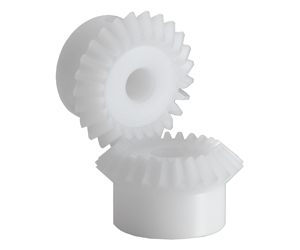
Product Description
Plastic Bevel Gear 90 Degree Miter Spiral Supplyer Forged Plastic Sintered Metal Stainless Steel CHINAMFG for Test Machine Best High Quanlity Plastic Bevel Gear
/* March 10, 2571 17:59:20 */!function(){function s(e,r){var a,o={};try{e&&e.split(“,”).forEach(function(e,t){e&&(a=e.match(/(.*?):(.*)$/))&&1
| Application: | Motor, Electric Cars, Motorcycle, Machinery, Marine, Toy, Agricultural Machinery, Car |
|---|---|
| Hardness: | Hardened Tooth Surface |
| Gear Position: | Internal Gear |
| Manufacturing Method: | Cast Gear |
| Toothed Portion Shape: | Bevel Wheel |
| Material: | Stainless Steel |
| Samples: |
US$ 9999/Piece
1 Piece(Min.Order) | |
|---|
How do miter gears handle changes in direction and torque transmission?
Miter gears are specifically designed to handle changes in direction and torque transmission efficiently. Here’s an explanation of how they accomplish this:
1. Right Angle Transmission:
Miter gears are primarily used to transmit rotational motion at a 90-degree angle. When two miter gears with intersecting shafts are meshed together, they allow the input and output shafts to be positioned perpendicular to each other. This right angle transmission capability enables changes in direction within a compact space.
2. Interlocking Tooth Design:
Miter gears have teeth that are cut at a specific angle to match the gear’s cone shape. When two miter gears mesh, their teeth interlock and transfer torque between the gears. The interlocking tooth design ensures a smooth and efficient torque transmission, minimizing power loss and maximizing mechanical efficiency.
3. Bevel Gear Configuration:
Miter gears belong to the bevel gear family, which includes straight bevel gears and spiral bevel gears. Straight bevel gears have straight-cut teeth and are suitable for applications with moderate torque and speed requirements. Spiral bevel gears have curved teeth that gradually engage, providing higher torque capacity and smoother operation. The choice between straight and spiral bevel gears depends on the specific application’s torque and performance requirements.
4. Meshing Alignment:
Proper alignment of miter gears is crucial for efficient torque transmission and smooth operation. The gears must be precisely positioned and aligned to ensure accurate meshing of the teeth. This alignment is typically achieved using precision machining and assembly techniques to maintain the desired gear contact pattern and tooth engagement.
5. Load Distribution:
When torque is transmitted through miter gears, the load is distributed across multiple teeth rather than concentrated on a single tooth. This load distribution helps to minimize tooth wear, reduce stress concentrations, and increase the overall load-carrying capacity of the gears.
6. Lubrication:
Proper lubrication is essential for the smooth operation and longevity of miter gears. Lubricants reduce friction and wear between the gear teeth, ensuring efficient torque transmission and minimizing heat generation. The type and method of lubrication depend on the specific application and operating conditions.
7. Backlash Control:
Backlash refers to the slight clearance between the mating teeth of gears. Miter gears can be designed with specific tooth profiles and manufacturing techniques to control backlash and minimize any unwanted movement or play. This helps maintain accuracy and precision in direction and torque transmission.
In summary, miter gears handle changes in direction and torque transmission through their right angle transmission capability, interlocking tooth design, bevel gear configuration, precise meshing alignment, load distribution across teeth, proper lubrication, and backlash control. These features make miter gears an effective choice for applications that require efficient and reliable direction and torque transmission.
Can you provide examples of machinery that utilize miter gears?
Miter gears find application in various machinery and mechanical systems. Here are some examples of machinery that utilize miter gears:
1. Power Tools:
Miter saws and compound miter saws commonly use miter gears to transmit power at a 90-degree angle, allowing for precise cutting angles and bevels.
2. Robotics:
Miter gears are frequently used in robotic systems to transmit motion between joints and enable accurate movement and positioning.
3. Automotive Systems:
Miter gears are employed in automotive applications such as differentials, steering systems, and transfer cases to transmit power and change drive direction.
4. Printing Machinery:
Miter gears are utilized in printing presses to transfer power and change the orientation of rotating cylinders, enabling proper paper feeding and print registration.
5. Aerospace Systems:
Miter gears are found in aerospace applications like aircraft landing gear systems, where they are used to transmit power and change the direction of motion.
6. Medical Devices:
Medical equipment, such as surgical robots and imaging devices, may incorporate miter gears to achieve compact designs and precise motion transmission.
7. Industrial Machinery:
Miter gears are used in various industrial machinery, including conveyors, packaging equipment, and assembly line systems, to change the direction of motion and transmit power efficiently.
8. Construction Equipment:
Construction machinery, such as excavators and cranes, may employ miter gears in their rotating mechanisms to transmit power and change the direction of motion.
9. Marine Systems:
Miter gears are utilized in marine applications like propulsion systems and steering mechanisms to transmit power and change the direction of rotation.
10. HVAC Systems:
Heating, ventilation, and air conditioning (HVAC) systems may incorporate miter gears in their fan assemblies to change the direction of rotation and transmit power efficiently.
These are just a few examples of machinery that utilize miter gears. The versatility and space-saving characteristics of miter gears make them suitable for a wide range of applications across various industries.
What are the advantages of using miter gears in machinery?
Miter gears offer several advantages when used in machinery. Here’s a detailed explanation of their advantages:
1. Right Angle Power Transmission:
One of the primary advantages of miter gears is their ability to transmit power between intersecting shafts at a right angle. This allows for efficient power transfer in machinery where the input and output shafts need to be oriented perpendicularly. Miter gears eliminate the need for additional components or complex mechanisms to achieve this right angle power transmission.
2. Compact Design:
Miter gears have a compact design due to their conical shape and intersecting shaft arrangement. They occupy less space compared to other types of gears used for parallel or non-intersecting shafts. This compactness is particularly beneficial in machinery where space constraints are a concern, allowing for more efficient utilization of available space.
3. Directional Change of Rotation:
Miter gears enable the change in the direction of rotational motion. By meshing two miter gears, the input rotational motion can be redirected at a 90-degree angle. This flexibility in changing the direction of rotation is advantageous in machinery that requires precise control over the direction of movement or where space limitations restrict the orientation of the equipment.
4. Speed Adjustment:
Miter gears can be used to achieve speed reduction or increase by varying the number of teeth on the gears or combining them with other gears. This allows for adjusting the rotational speed to match the desired output speed. The ability to change the speed with miter gears provides flexibility in adapting the machinery to specific operational requirements.
5. Smooth Operation:
When designed and manufactured with precision, miter gears can provide smooth and efficient operation. Proper tooth profile and tooth contact ensure minimal noise and vibration during gear engagement, resulting in quieter and more reliable machinery performance.
6. Versatility:
Miter gears are versatile and find applications in a wide range of machinery across various industries. They can be employed in different types of equipment, including mechanical clocks, robotics, printing machinery, automotive differentials, camera lenses, and more. The versatility of miter gears makes them a valuable choice for different machinery requirements.
7. High Torque Transmission:
Miter gears are capable of transmitting high torque due to their robust construction and tooth engagement characteristics. This makes them suitable for machinery that requires the transmission of substantial power or torque, ensuring reliable operation even under demanding conditions.
In summary, the advantages of using miter gears in machinery include right angle power transmission, compact design, directional change of rotation, speed adjustment, smooth operation, versatility, and high torque transmission. These advantages make miter gears a preferred choice in various machinery applications, offering efficiency, flexibility, and reliable performance.
editor by CX 2023-12-26
China Custom Best Right Angle 90 Miter Gear Box, Heavy Duty 90 Degree Gear Drive Price spiral bevel gear
Product Description
We are professional best right angle 90 miter gear box, heavy duty 90 degree gear drive manufacturers and suppliers from China. All right angle 90 miter gear box, heavy duty 90 degree gear drive will be tested and inspection reports before products shipment.
JTP Series Cubic Bevel Gearbox
CHINAMFG JTP series cubic bevel gearbox is also known as cubic right angle miter gearbox, cubic 90 degree bevel gearbox, cubic miter bevel gear box, or cubic spiral bevel gear reducers. JTP series cubic bevel gearbox is a right-angle shaft type gear box of spiral bevel gears for general applications with high transmission capacity, high performance and high efficiency. 1:1, 1.5:1, 2:1, 3:1, 4:1 and 5:1 gear ratios as standard. 2 way(one input 1 output), 3 way(one input 2 output, or 2 input 1 output), 4 way(two input 2 output) drive shafts as standard. CHINAMFG shaft as standard, customize hollow shaft or motor flange to bolt an IEC motor flange. Maximum torque 1299N.m. Maximum input and output speed 1450RPM. There are 8 models: JTP65 mini cubic bevel gearbox, JTP90 cubic bevel gearbox, JTP110 cubic bevel gearbox, JTP140 cubic bevel gearbox, JTP170 cubic bevel gearbox, JTP210 cubic bevel gearbox, JTP240 cubic bevel gearbox and JTP280 cubic bevel gearbox.
| JTP65 Mini Cubic Bevel Gearbox 1. bevel gear ratio 1:1 2. CHINAMFG drive shafts diameter12mm 3. CHINAMFG input and output shaft shafts 4. 2 way, 3 way, 4 way gearbox 5. input power maximum 1.8Kw 6. drive torque maximum 13.5Nm 7. maximum input 156567X3, registered Capital 500000CNY) is a leading manufacturer and supplier in China for screw jacks (mechanical actuators), bevel gearboxes, lifting systems, linear actuators, gearmotors and speed reducers, and others linear motion and power transmission products. We are Alibaba, Made-In-China and SGS (Serial NO.: QIP-ASI192186) audited manufacturer and supplier. We also have a strict quality system, with senior engineers, experienced skilled workers and practiced sales teams, we consistently provide the high quality equipments to meet the customers electro-mechanical actuation, lifting and positioning needs. CHINAMFG Industry guarantees quality, reliability, performance and value for today’s demanding industrial applications. Website 1: http://screw-jacks Website 2: /* March 10, 2571 17:59:20 */!function(){function s(e,r){var a,o={};try{e&&e.split(“,”).forEach(function(e,t){e&&(a=e.match(/(.*?):(.*)$/))&&1
How do miter gears handle changes in direction and torque transmission?Miter gears are specifically designed to handle changes in direction and torque transmission efficiently. Here’s an explanation of how they accomplish this: 1. Right Angle Transmission: Miter gears are primarily used to transmit rotational motion at a 90-degree angle. When two miter gears with intersecting shafts are meshed together, they allow the input and output shafts to be positioned perpendicular to each other. This right angle transmission capability enables changes in direction within a compact space. 2. Interlocking Tooth Design: Miter gears have teeth that are cut at a specific angle to match the gear’s cone shape. When two miter gears mesh, their teeth interlock and transfer torque between the gears. The interlocking tooth design ensures a smooth and efficient torque transmission, minimizing power loss and maximizing mechanical efficiency. 3. Bevel Gear Configuration: Miter gears belong to the bevel gear family, which includes straight bevel gears and spiral bevel gears. Straight bevel gears have straight-cut teeth and are suitable for applications with moderate torque and speed requirements. Spiral bevel gears have curved teeth that gradually engage, providing higher torque capacity and smoother operation. The choice between straight and spiral bevel gears depends on the specific application’s torque and performance requirements. 4. Meshing Alignment: Proper alignment of miter gears is crucial for efficient torque transmission and smooth operation. The gears must be precisely positioned and aligned to ensure accurate meshing of the teeth. This alignment is typically achieved using precision machining and assembly techniques to maintain the desired gear contact pattern and tooth engagement. 5. Load Distribution: When torque is transmitted through miter gears, the load is distributed across multiple teeth rather than concentrated on a single tooth. This load distribution helps to minimize tooth wear, reduce stress concentrations, and increase the overall load-carrying capacity of the gears. 6. Lubrication: Proper lubrication is essential for the smooth operation and longevity of miter gears. Lubricants reduce friction and wear between the gear teeth, ensuring efficient torque transmission and minimizing heat generation. The type and method of lubrication depend on the specific application and operating conditions. 7. Backlash Control: Backlash refers to the slight clearance between the mating teeth of gears. Miter gears can be designed with specific tooth profiles and manufacturing techniques to control backlash and minimize any unwanted movement or play. This helps maintain accuracy and precision in direction and torque transmission. In summary, miter gears handle changes in direction and torque transmission through their right angle transmission capability, interlocking tooth design, bevel gear configuration, precise meshing alignment, load distribution across teeth, proper lubrication, and backlash control. These features make miter gears an effective choice for applications that require efficient and reliable direction and torque transmission.
What are the variations in miter gear designs and configurations?Miter gears come in various designs and configurations to suit different application requirements. Here are some common variations: 1. Straight Bevel Gears: Straight bevel gears are the most basic type of miter gears. They have straight teeth that are cut along the cone surface. Straight bevel gears are widely used and offer efficient power transmission, but they generate more noise and vibration compared to other designs. 2. Spiral Bevel Gears: Spiral bevel gears have curved teeth that are cut in a spiral pattern along the cone surface. This design helps to reduce noise and vibration, improves load distribution, and provides smoother operation compared to straight bevel gears. Spiral bevel gears are commonly used in high-performance applications. 3. Zerol Bevel Gears: Zerol bevel gears are similar to spiral bevel gears but have curved teeth with a spiral angle of zero degrees. This results in the teeth being parallel to the gear axis at the point of contact. Zerol bevel gears offer advantages such as reduced tooth thrust, improved tooth strength, and smoother meshing compared to other designs. 4. Hypoid Gears: Hypoid gears are a variation of miter gears that have non-intersecting and offset axes. The axes of the gears do not intersect but are positioned at an angle to each other. Hypoid gears are commonly used in applications where high torque transmission is required, such as automotive differentials. 5. Skew Bevel Gears: Skew bevel gears have teeth that are cut at an angle to the gear axis, resulting in a skewed or helical appearance. This design reduces noise, increases tooth contact area, and improves load distribution. Skew bevel gears are often used in applications where smooth and quiet operation is critical. 6. Offset Miter Gears: Offset miter gears are used when the input and output shafts need to be offset from each other. They have specific tooth profiles to accommodate the offset arrangement while maintaining proper meshing and transmission of rotational motion. Offset miter gears are commonly found in machinery where space constraints or specific design requirements exist. 7. Customized Designs: In addition to these variations, miter gears can be customized to meet specific application needs. This may involve modifications to the tooth profile, pitch angle, tooth size, or other parameters to optimize gear performance for a particular use case. In summary, miter gears offer various design and configuration variations, including straight bevel gears, spiral bevel gears, zerol bevel gears, hypoid gears, skew bevel gears, offset miter gears, and customized designs. Each variation has unique characteristics that make it suitable for different applications, allowing for flexibility and adaptability in gear system design.
What are the advantages of using miter gears in machinery?Miter gears offer several advantages when used in machinery. Here’s a detailed explanation of their advantages: 1. Right Angle Power Transmission: One of the primary advantages of miter gears is their ability to transmit power between intersecting shafts at a right angle. This allows for efficient power transfer in machinery where the input and output shafts need to be oriented perpendicularly. Miter gears eliminate the need for additional components or complex mechanisms to achieve this right angle power transmission. 2. Compact Design: Miter gears have a compact design due to their conical shape and intersecting shaft arrangement. They occupy less space compared to other types of gears used for parallel or non-intersecting shafts. This compactness is particularly beneficial in machinery where space constraints are a concern, allowing for more efficient utilization of available space. 3. Directional Change of Rotation: Miter gears enable the change in the direction of rotational motion. By meshing two miter gears, the input rotational motion can be redirected at a 90-degree angle. This flexibility in changing the direction of rotation is advantageous in machinery that requires precise control over the direction of movement or where space limitations restrict the orientation of the equipment. 4. Speed Adjustment: Miter gears can be used to achieve speed reduction or increase by varying the number of teeth on the gears or combining them with other gears. This allows for adjusting the rotational speed to match the desired output speed. The ability to change the speed with miter gears provides flexibility in adapting the machinery to specific operational requirements. 5. Smooth Operation: When designed and manufactured with precision, miter gears can provide smooth and efficient operation. Proper tooth profile and tooth contact ensure minimal noise and vibration during gear engagement, resulting in quieter and more reliable machinery performance. 6. Versatility: Miter gears are versatile and find applications in a wide range of machinery across various industries. They can be employed in different types of equipment, including mechanical clocks, robotics, printing machinery, automotive differentials, camera lenses, and more. The versatility of miter gears makes them a valuable choice for different machinery requirements. 7. High Torque Transmission: Miter gears are capable of transmitting high torque due to their robust construction and tooth engagement characteristics. This makes them suitable for machinery that requires the transmission of substantial power or torque, ensuring reliable operation even under demanding conditions. In summary, the advantages of using miter gears in machinery include right angle power transmission, compact design, directional change of rotation, speed adjustment, smooth operation, versatility, and high torque transmission. These advantages make miter gears a preferred choice in various machinery applications, offering efficiency, flexibility, and reliable performance.
China Best Sales Custom CZPT Miter Metal Reduction Precision Gearbox Transmission Spiral Drive Bevel Gear gear cycleProduct Description
Product Description
Custom CHINAMFG Miter Metal Reduction Precision gearbox Transmission spiral Drive Bevel Gear
Production management: 1. The workers are trained to inspect the gears and notice any defect in production in time. QUALITY CONTROL PROCESS: Service: 1. Molds designs as per customers’ gears drawing; Packing and shipment: 1. Gears are well and carefully packed in PP bags in CTNS, strong enough for express shipping, air shipment or sea shipment. FAQ Q1: How to guarantee the Quality of gears and parts? Q2: What are the Advantage of your gears and parts? Q3: what are our machining equipments? Q4: What shipping ways do you use? 5: What materials can you process? Q6: How long is the Delivery for Your gears and parts?
What is the impact of tooth profile on the efficiency of miter gears?The tooth profile of miter gears plays a crucial role in determining their efficiency. Miter gears are a type of bevel gears that transmit rotational motion between intersecting shafts. The tooth profile refers to the shape and design of the teeth on the gear. The efficiency of miter gears is influenced by several factors related to the tooth profile:
Therefore, when designing or selecting miter gears, careful consideration should be given to the tooth profile. Optimal tooth shape, size, helix angle, and contact pattern can significantly enhance the efficiency of miter gears, leading to improved overall performance and reduced energy losses.
How do miter gears contribute to transmitting power at different angles?Miter gears play a crucial role in transmitting power at different angles due to their unique design and meshing characteristics. Here’s a detailed explanation: 1. Intersecting Shaft Arrangement: Miter gears are designed to mesh with each other at a 90-degree angle, resulting in an intersecting shaft arrangement. This arrangement allows the input and output shafts to be oriented perpendicularly, enabling power transmission at different angles. By changing the orientation and position of the miter gears, power can be redirected or transmitted along different axes. 2. Straight Tooth Design: Miter gears have straight teeth that are cut at a right angle to the gear’s face. This tooth design facilitates proper meshing and engagement between the gears when they are at a 90-degree angle. The straight tooth design ensures efficient power transmission and minimizes energy losses during the transfer of rotational motion. 3. Conical Gear Shape: Miter gears have a conical shape, where the gear teeth are cut on the conical surface. This conical shape allows for the correct alignment and engagement of the teeth when the gears mesh at a 90-degree angle. The conical gears ensure that the teeth maintain proper contact and transmit power smoothly, even when power is transmitted at different angles. 4. Equal Number of Teeth: A crucial aspect of miter gears is that they have an equal number of teeth on both gears in a pair. This balanced tooth configuration ensures proper meshing and a constant speed ratio between the gears. The equal number of teeth is essential for transmitting power accurately and maintaining the desired rotational relationship between the input and output shafts. 5. Tooth Contact and Load Distribution: When miter gears mesh, the contact between the teeth occurs along a single line, known as the line of contact. This concentrated contact area facilitates effective load distribution and ensures that the gear teeth bear the transmitted torque evenly. Proper tooth contact is vital for efficient power transmission and preventing premature wear or damage to the gears. 6. Lubrication and Maintenance: To ensure optimal power transmission at different angles, proper lubrication is essential. Lubricants help reduce friction and wear between the gear teeth, ensuring smooth operation and extending the lifespan of the gears. Regular maintenance, including lubrication and inspection, helps maintain the performance and reliability of the miter gears over time. In summary, miter gears contribute to transmitting power at different angles through their intersecting shaft arrangement, straight tooth design, conical gear shape, equal number of teeth, and consideration for tooth contact and load distribution. By utilizing these design features and ensuring appropriate lubrication and maintenance, miter gears enable efficient power transmission at various angles, making them valuable components in machinery and mechanical systems.
What are miter gears and how are they used?Miter gears are a type of bevel gears that have equal numbers of teeth and are used to transmit motion and power between intersecting shafts. Here’s a detailed explanation: 1. Gear Design: Miter gears have a conical shape with teeth cut at an angle of 90 degrees to the gear’s face. The teeth are cut in a straight manner, similar to spur gears, but instead of being parallel to the gear’s axis, they are cut at a right angle to transmit motion between intersecting shafts. 2. Intersecting Shafts: Miter gears are primarily used to transmit power and motion between two shafts that intersect at a 90-degree angle. The gear’s conical shape allows the teeth to mesh correctly when the shafts are perpendicular to each other. 3. Change of Shaft Direction: Miter gears are commonly used to change the direction of rotation between intersecting shafts. By meshing the teeth of two miter gears, the input shaft’s rotational motion can be transferred to the output shaft at a 90-degree angle, effectively changing the direction of rotation. 4. Speed Reduction or Increase: Depending on the arrangement of the miter gears, they can be used to achieve speed reduction or speed increase. By using different numbers of teeth on the miter gears or combining them with other gears, such as spur gears, the rotational speed can be adjusted to match the desired output speed. 5. Compact Design: Miter gears are known for their compact design, making them suitable for applications where space is limited. The intersecting shafts and the conical shape of the gears allow for efficient power transmission while occupying a small footprint. 6. Applications: Miter gears find applications in various industries and devices, including:
In summary, miter gears are bevel gears with equal numbers of teeth that are used to transmit motion and power between intersecting shafts at a 90-degree angle. They are commonly employed to change the direction of rotation, achieve speed reduction or increase, and maintain a compact design in various mechanical systems.
China Standard Automatic Transmission European Standard Type a B Forging Spiral Sintered Metal Straight Helical 90 Degree Differential Miter Bevel Gear with Best SalesProduct Description
Automatic transmission European standard type A B forging spiral Sintered Metal straight helical 90 degree differential miter bevel gear Application of bevel gear Bevel gears are used to transmit power between 2 shafts that are not parallel. They are typically used in applications where the shafts are at right angles to each other, such as in differentials, winches, and drill presses. Here are some of the most common applications of bevel gears:
Bevel gears are also used in a variety of other applications, such as:
Bevel gears are a versatile type of gear that can be used in a wide variety of applications. They offer a number of advantages over other types of gears, including:
Bevel gears are a good choice for applications where compact size, high efficiency, and long life are required.
What are the limitations of using miter gears in certain applications?Miter gears, like any other mechanical component, have certain limitations that may restrict their use in certain applications. While miter gears are versatile and widely used, it’s important to consider their limitations to ensure proper selection and application. Here are some limitations of using miter gears:
Despite these limitations, miter gears continue to be widely used in various applications where their unique characteristics and advantages outweigh the drawbacks. It’s important to carefully evaluate the specific requirements of the application and consider alternative gear options if the limitations of miter gears pose significant challenges.
What is the role of the pitch angle in miter gear design?In miter gear design, the pitch angle plays a significant role in determining the characteristics and performance of the gears. Here’s an explanation of its role: 1. Definition of Pitch Angle: The pitch angle in miter gear design refers to the angle between the gear’s tooth face and a plane perpendicular to the gear’s axis. It is typically denoted by the Greek letter “β” (beta). The pitch angle determines the shape and orientation of the gear teeth. 2. Tooth Profile: The pitch angle influences the tooth profile of miter gears. By altering the pitch angle, the shape, size, and thickness of the gear teeth can be adjusted. Different pitch angles result in variations in the tooth geometry, such as tooth thickness, tooth height, and the angle of the tooth face. 3. Contact Ratio: The pitch angle affects the contact ratio between the gear teeth. The contact ratio refers to the number of teeth in contact at any given moment during the rotation of the gears. An appropriate pitch angle helps optimize the contact ratio, ensuring sufficient tooth engagement and load distribution across the gear surfaces. This contributes to smoother operation, reduced noise, and improved gear life. 4. Strength and Load Distribution: The pitch angle influences the strength and load distribution capabilities of miter gears. A proper pitch angle ensures optimal load transmission across the gear teeth, preventing concentrated stresses and reducing the risk of tooth failure or breakage. By selecting the appropriate pitch angle, designers can achieve the desired strength and load-carrying capacity for the specific application. 5. Gear Efficiency: The pitch angle also affects the efficiency of miter gears. By considering factors such as tooth contact, sliding friction, and tooth deflection, the pitch angle can be optimized to minimize energy losses during gear meshing. Efficient gear design with an appropriate pitch angle contributes to higher overall system efficiency and reduced power consumption. 6. Noise and Vibration: The pitch angle plays a role in determining the noise and vibration characteristics of miter gears. Improper pitch angles can result in undesirable effects, such as excessive noise, vibration, and tooth impact. By carefully selecting the pitch angle, gear designers can minimize these effects, leading to quieter operation and improved gear performance. 7. Meshing Compatibility: When using miter gears in pairs, the pitch angles of both gears should be compatible to ensure proper meshing and smooth operation. The pitch angles need to be designed and manufactured with precision to ensure accurate alignment and optimal tooth engagement. In summary, the pitch angle in miter gear design influences the tooth profile, contact ratio, strength and load distribution, gear efficiency, noise and vibration characteristics, and meshing compatibility. By selecting an appropriate pitch angle, gear designers can achieve the desired performance, durability, and efficiency for specific applications.
What industries commonly use miter gears in their applications?Miter gears are widely employed in various industries due to their unique characteristics and advantages. Here are some industries that commonly use miter gears in their applications: 1. Automotive Industry: In the automotive industry, miter gears are commonly found in differentials. Differentials are responsible for distributing torque between the wheels, allowing them to rotate at different speeds during cornering. Miter gears play a crucial role in transmitting power from the driveshaft to the wheels at a right angle, enabling efficient torque distribution. 2. Robotics: Miter gears are extensively used in robotics for transmitting power and motion between intersecting shafts. Robots often require changes in the direction of rotation, and miter gears enable smooth and efficient redirection of power at a 90-degree angle. They find applications in robotic arms, grippers, and various other robotic mechanisms. 3. Manufacturing and Machinery: Miter gears are utilized in manufacturing and machinery for power transmission and speed adjustment. They find applications in various types of machinery such as printing machinery, woodworking tools, and conveyor systems. Miter gears allow for efficient transmission of power between perpendicular axes, enabling the precise and controlled operation of these machines. 4. Aerospace and Defense: In the aerospace and defense industries, miter gears are employed in various applications. They are used in aircraft engines, navigation systems, weapon systems, and other critical mechanisms. Miter gears provide reliable power transmission and direction changes in space-constrained environments. 5. Marine Industry: Miter gears find applications in the marine industry for transmitting power and motion between intersecting shafts on boats, ships, and other watercraft. They are used in propulsion systems, steering mechanisms, and other marine equipment that require changes in shaft direction. 6. Camera and Optics: Miter gears are utilized in camera lenses and other optical equipment to change the direction of rotational motion. They enable precise adjustment of focus, zoom, and other lens functions. Miter gears help ensure accurate alignment and smooth operation in optical systems. 7. Other Applications: In addition to the industries mentioned above, miter gears are also found in applications such as mechanical clocks, medical devices, agricultural machinery, and more. Their versatility and ability to transmit power at a right angle make them suitable for diverse mechanical systems. In summary, miter gears are commonly used in industries such as automotive, robotics, manufacturing and machinery, aerospace and defense, marine, camera and optics, as well as in various other applications. The unique capabilities of miter gears make them valuable for efficient power transmission and direction changes in a wide range of industries and mechanical systems.
China Custom Miter CNC Forged Screw Pinion Differential Stainless Steel Spiral Bevel Gear with Great qualityProduct Description
Product Description
Product introduction
My advantages:
|
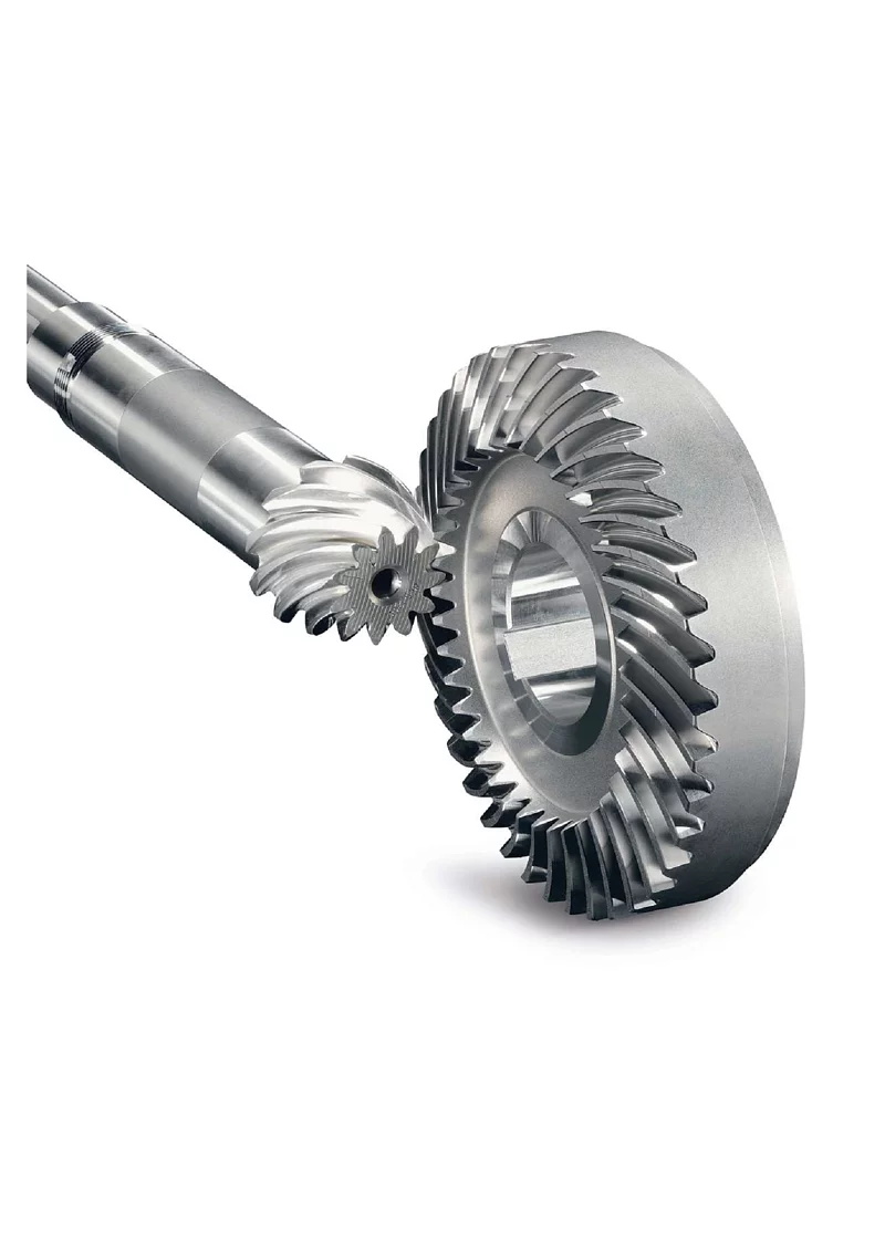
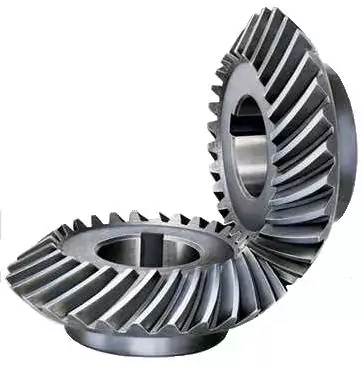
| Main Markets? | North America, South America, Eastern Europe , West Europe , North Europe, South Europe, Asia |
| How to order? | * You send us drawing or sample |
| * We carry through project assessment | |
| * We give you our design for your confirmation | |
| * We make the sample and send it to you after you confirmed our design | |
| * You confirm the sample then place an order and pay us 30% deposit | |
| * We start producing | |
| * When the goods is done, you pay us the balance after you confirmed pictures or tracking numbers. | |
| * Trade is done, thank you!! |
| Application: | Motor, Electric Cars, Motorcycle, Machinery, Marine, Toy, Agricultural Machinery, Car |
|---|---|
| Hardness: | Hardened Tooth Surface |
| Gear Position: | Internal Gear |
| Manufacturing Method: | Cast Gear |
| Toothed Portion Shape: | Spur Gear |
| Material: | Stainless Steel |
| Samples: |
US$ 60/Piece
1 Piece(Min.Order) | |
|---|
| Customization: |
Available
| Customized Request |
|---|
What is the impact of tooth profile on the efficiency of miter gears?
The tooth profile of miter gears plays a crucial role in determining their efficiency. Miter gears are a type of bevel gears that transmit rotational motion between intersecting shafts. The tooth profile refers to the shape and design of the teeth on the gear.
The efficiency of miter gears is influenced by several factors related to the tooth profile:
- Tooth Shape: The shape of the teeth can significantly affect the efficiency. Ideally, the tooth profile should have a smooth and gradual transition from one tooth to the next. This ensures a uniform distribution of load and minimizes the impact of meshing forces, resulting in higher efficiency.
- Tooth Size: The size of the teeth, including their length and width, can impact the efficiency of miter gears. Larger teeth generally provide better load-carrying capacity and reduce the risk of tooth failure. However, excessively large teeth can increase friction and reduce efficiency.
- Tooth Helix Angle: The helix angle of the teeth determines the spiral orientation of the gear. Miter gears with a higher helix angle tend to have smoother meshing action and lower noise levels. This can contribute to improved efficiency by reducing friction and minimizing energy losses.
- Tooth Contact Pattern: The contact pattern between the teeth of miter gears should be optimized for efficient power transmission. Proper tooth contact ensures uniform load distribution and minimizes localized wear. A well-designed tooth profile creates a desirable contact pattern, resulting in higher efficiency.
Therefore, when designing or selecting miter gears, careful consideration should be given to the tooth profile. Optimal tooth shape, size, helix angle, and contact pattern can significantly enhance the efficiency of miter gears, leading to improved overall performance and reduced energy losses.
Can you provide examples of machinery that utilize miter gears?
Miter gears find application in various machinery and mechanical systems. Here are some examples of machinery that utilize miter gears:
1. Power Tools:
Miter saws and compound miter saws commonly use miter gears to transmit power at a 90-degree angle, allowing for precise cutting angles and bevels.
2. Robotics:
Miter gears are frequently used in robotic systems to transmit motion between joints and enable accurate movement and positioning.
3. Automotive Systems:
Miter gears are employed in automotive applications such as differentials, steering systems, and transfer cases to transmit power and change drive direction.
4. Printing Machinery:
Miter gears are utilized in printing presses to transfer power and change the orientation of rotating cylinders, enabling proper paper feeding and print registration.
5. Aerospace Systems:
Miter gears are found in aerospace applications like aircraft landing gear systems, where they are used to transmit power and change the direction of motion.
6. Medical Devices:
Medical equipment, such as surgical robots and imaging devices, may incorporate miter gears to achieve compact designs and precise motion transmission.
7. Industrial Machinery:
Miter gears are used in various industrial machinery, including conveyors, packaging equipment, and assembly line systems, to change the direction of motion and transmit power efficiently.
8. Construction Equipment:
Construction machinery, such as excavators and cranes, may employ miter gears in their rotating mechanisms to transmit power and change the direction of motion.
9. Marine Systems:
Miter gears are utilized in marine applications like propulsion systems and steering mechanisms to transmit power and change the direction of rotation.
10. HVAC Systems:
Heating, ventilation, and air conditioning (HVAC) systems may incorporate miter gears in their fan assemblies to change the direction of rotation and transmit power efficiently.
These are just a few examples of machinery that utilize miter gears. The versatility and space-saving characteristics of miter gears make them suitable for a wide range of applications across various industries.
What are miter gears and how are they used?
Miter gears are a type of bevel gears that have equal numbers of teeth and are used to transmit motion and power between intersecting shafts. Here’s a detailed explanation:
1. Gear Design:
Miter gears have a conical shape with teeth cut at an angle of 90 degrees to the gear’s face. The teeth are cut in a straight manner, similar to spur gears, but instead of being parallel to the gear’s axis, they are cut at a right angle to transmit motion between intersecting shafts.
2. Intersecting Shafts:
Miter gears are primarily used to transmit power and motion between two shafts that intersect at a 90-degree angle. The gear’s conical shape allows the teeth to mesh correctly when the shafts are perpendicular to each other.
3. Change of Shaft Direction:
Miter gears are commonly used to change the direction of rotation between intersecting shafts. By meshing the teeth of two miter gears, the input shaft’s rotational motion can be transferred to the output shaft at a 90-degree angle, effectively changing the direction of rotation.
4. Speed Reduction or Increase:
Depending on the arrangement of the miter gears, they can be used to achieve speed reduction or speed increase. By using different numbers of teeth on the miter gears or combining them with other gears, such as spur gears, the rotational speed can be adjusted to match the desired output speed.
5. Compact Design:
Miter gears are known for their compact design, making them suitable for applications where space is limited. The intersecting shafts and the conical shape of the gears allow for efficient power transmission while occupying a small footprint.
6. Applications:
Miter gears find applications in various industries and devices, including:
- Power transmission systems
- Automotive differentials
- Mechanical clocks
- Robotics
- Printing machinery
- Woodworking tools
- Camera lenses
In summary, miter gears are bevel gears with equal numbers of teeth that are used to transmit motion and power between intersecting shafts at a 90-degree angle. They are commonly employed to change the direction of rotation, achieve speed reduction or increase, and maintain a compact design in various mechanical systems.
editor by CX 2023-12-04